files
How to prepare an STL file
Five checks before uploading: closed mesh, units in mm, export resolution, walls from 0.8 mm up and overhangs within 45°.
Marcello BilliAugust 18, 202611 min
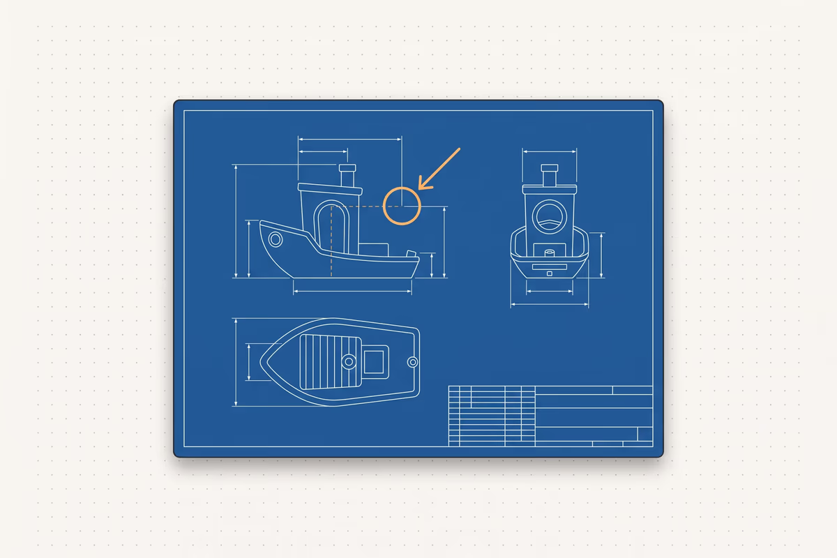
To prepare an STL file for 3D printing you need five checks: a closed mesh (watertight), units in millimetres, the right export resolution, wall thickness above the process minimum and overhangs within 45 degrees. If all five are in order, you upload the model and get a price in seconds. All the real numbers, in mm, section by section.
In short
- The 5 checks: closed (watertight) mesh, units in mm, export resolution, wall thickness, overhangs within 45 degrees.
- STL doesn't store units: typical errors are x25.4 (inches) and x1000 (Blender in metres). Check the bounding box on upload.
- Minimum wall: FDM 0.8 mm (multiples of 0.4), SLA 0.4-1.0 mm, SLS 0.7-1.0 mm. Never below 0.5 mm.
- FDM tolerances: general clearance ~0.3 mm, press-fit 0.1-0.2 mm; holes come out 0.1-0.3 mm undersized.
- Export binary STL, chord deviation 0.01-0.05 mm, file under 20 MB.
Getting a slicer error? Start here
Almost every file problem comes down to three causes: wrong units, an open mesh and walls below the minimum thickness. Identify the symptom, apply the quick fix, then jump to the right section for the details.
| Symptom | Cause | 2-minute fix |
|---|---|---|
| The part is 25 or 1000 times too big or too small | Units of measurement (STL doesn't store them) | Set mm on export and check the bounding box on upload |
| The slicer says "not manifold" or "not watertight" | Open mesh, duplicate geometry or flipped normals | Slicer auto-repair, then 3D Builder |
| A wall or a detail disappears after slicing | Thickness below the process minimum | Bring the wall to at least 0.8 mm in FDM |
| Faceted curves, round holes shaped like stop signs | Export resolution too low | Lower the chord deviation in your CAD and re-export |
| Drooping overhangs or supports everywhere | Geometry beyond 45 degrees | Reorient the part or turn the edge into a 45-degree chamfer |
Units and scale: why does the part come out 25 or 1000 times the wrong size?
The STL format does not store units of measurement, and that's the number one cause of wrong-sized parts: the bounding box in millimetres is also the first check we run on files uploaded to our instant quote. If you model in inches and the slicer reads millimetres, the part comes out 25.4 times too small. If you export from Blender, which works in metres, it comes out 1000 times too big. There is only one rule: think, model and export in millimetres, always.
- In your CAD: set both the document and the export to mm before saving the STL.
- In Blender: set the unit scale to 0.001, or scale the model x1000 and apply the scale with Ctrl+A before exporting.
- Quick fix in the slicer: if the part arrives in inches, scale it by 2540% to bring it to mm.
- Always check the bounding box: as soon as you upload the file, look at its dimensions in mm. If they're off by a factor of 25 or 1000, it's a units problem.
Want to eliminate the problem at the root? Export to 3MF instead of STL: it carries its units with it, so no scale errors.
Closed, manifold mesh: the errors that stop a print
A watertight, manifold mesh is the number one requirement for printing. Manifold means every edge is shared by exactly two faces: if an edge touches three or more, the slicer can't tell inside from outside. The mental test is simple: fill the model with water — if it leaks, it isn't closed.
The most common causes when the slicer rejects a file:
- Holes and open edges: the mesh isn't sealed.
- Flipped normals: some faces point inwards and the slicer reads the part inside out (typical on hollowed models).
- Overlapping shells or duplicate geometry: often leftovers from boolean operations.
- Zero-thickness surfaces and naked edges: exporting from an open surface (in Rhino, an unclosed polysurface) leaves the mesh open.
The fix at the source: before exporting, merge everything into one closed solid with a boolean. Careful — two separate bodies that touch are not watertight: they need to be truly fused, not just placed against each other.
How to repair an STL file: which tools, and in what order?
When the slicer reports errors, work from the fastest tool to the most thorough. In most cases the first step is enough.
| Tool | What it does | When to use it |
|---|---|---|
| Slicer auto-fix | Repairs automatically (PrusaSlicer: "Fix through Netfabb"; Cura: "Make Manifold") | First attempt, solves the vast majority of cases |
| Microsoft 3D Builder | One-click repair of holes and normals, free on Windows | Simple holes and flipped normals |
| Meshmixer (Inspector) | Auto Repair All, then Make Solid for a sealed solid | Multiple holes and separate shells |
| Netfabb | Deep repairs on shells and edges | Complex industrial meshes |
| Blender + 3D-Print Toolbox | Full diagnostics and Ctrl+N to recalculate normals | Total control over difficult meshes |
The file is clean when the Inspector shows no red markers left and the model looks solid, not transparent.
Golden rule: repair at the source. If you can re-export closed geometry from your CAD, that beats any patch applied to the mesh. 3D scans and STLs with several grouped bodies are the classic causes of a file that can't be fixed downstream.
STL export resolution: no faceted curves, no 200 MB files
The right question isn't "how many triangles" but how much chord deviation: how far the flat triangles are allowed to stray from the true curve. Values that work for almost everything: chord 0.01-0.05 mm and angular around 1 degree. The canonical rule is a chord equal to 1/20 of the layer height, never below 0.001 mm (below that, you're only bloating the file).
Concrete presets for the most common CAD packages:
- Fusion 360: Refinement High, or a surface deviation of about 0.01 mm.
- SolidWorks: Save As, STL, Binary format, sliders towards Fine.
- Creo: chord height 0.01, angle control 0.25.
- Onshape: chordal 0.1, angular 1, minimum facet 0.1.
Always export binary STL, not ASCII: same geometry, a file 4-5 times lighter. Aim for a file under 20 MB. Above 40 MB you're overloading the slicer for no gain, because the printer can't resolve that detail anyway. And if curves come out faceted, raise the resolution at the source in your CAD, not by patching the mesh afterwards.
Minimum wall thickness and fine details: the numbers for each process
Minimum wall thickness depends on the process, and this is the number many services hide behind a generic "see the datasheet". Here are the real values to respect from the design stage.
| Process | Minimum wall | Notes |
|---|---|---|
| FDM | 0.8 mm (2 perimeters with a 0.4 nozzle) | In multiples of 0.4 (0.8 / 1.2 / 1.6); 1.2 mm or more if structural |
| SLA (resin) | 0.4-0.5 mm supported, 1.0 mm unsupported | Finer is possible, but fragile below the threshold |
| SLS | 0.7-1.0 mm (minimum about 0.7) | No supports, the powder holds the part |
| MJF | 0.5-0.7 mm | Good balance of detail and strength |
The absolute floor is 0.5 mm: never go below it. And watch out for a trap you can't see: a 1.0 mm wall with a 0.4 nozzle leaves internal voids (two full passes don't fit), so on FDM go with 1.2 mm. For fine details:
- Text in FDM: at least 0.6 mm wide for about 2 mm of height.
- Vertical holes: from 3 mm diameter upwards.
- SLA: engraved details 0.15 mm, embossed 0.1 mm.
- Pins in FDM: below 5 mm diameter they snap; fillet them at the base or use an inserted metal pin.
For how each filament actually performs, the real values are in our materials guide; to pick a filament based on what the part has to do, see the guide on which material for 3D printing.
One principle worth more than infill: for strength, increase the perimeters (the outer walls) first, not the infill. Stress lives on the skin of the part, and an extrusion width of 100-150% of the nozzle diameter (0.4-0.6 mm on a 0.4 nozzle) is the sweet spot.
Tolerances and clearances: parts that fit together or move
If two parts have to mate, don't model them at the same nominal size: they'll fuse into a single block. You need clearance, and in FDM it has to be designed in, because holes come out slightly undersized. Apply the clearance to one part only: keep the pin at 5.0 mm and take the hole to 5.3 mm for 0.3 mm of clearance.
| Fit (FDM) | Recommended clearance |
|---|---|
| General fit | about 0.3 mm |
| Sliding or moving parts | 0.3-0.5 mm |
| Press-fit | 0.1-0.2 mm |
| Pocket for an insert or nut | 0.1 mm per side |
For holes, oversize by diameter: below 6 mm add 0.1-0.3 mm, between 6 and 25 mm add 0.2-0.4 mm, above 25 mm from 0.5 to 1.0 mm. In general, FDM holes come out 0.1-0.3 mm undersized: design them about 0.25 mm oversize or ream them after printing. Typical FDM tolerance is around 0.2-0.3 mm; in SLA it's about 0.2%.
Orientation and supports: the 45-degree rule (and how to avoid supports)
Beyond 45 degrees from vertical, each new layer rests on less than half of the previous one and droops: that's where supports come in (at 45 degrees, notes Protolabs Network, the layer is still 50% supported). Well-cooled PLA reaches 55-60 degrees, PETG 45-50, ABS and nylon sit around 40-45. Horizontal bridges span freely up to about 10 mm safely, and up to 20-25 mm on a well-tuned machine.
Orientation, though, is first and foremost a strength decision. FDM is anisotropic: according to Protolabs Network, strength in the XY plane is typically 4-5 times the strength along the Z axis (between layers), and the gap varies with material and settings. Orient the part so the load pulls along the layers, where it holds best, not across them. Three tricks that eliminate supports at the design stage:
- A 45-degree chamfer instead of an overhang: it's self-supporting.
- A chamfer on the edge touching the build plate: kills elephant's foot.
- Teardrop-shaped horizontal holes: every layer supports itself, no supports inside the hole.
In SLA the story changes: the layers are chemically bonded and the part is nearly isotropic, so orientation is mostly about controlling surface finish and support marks.
Resin (SLA): hollowing the model and adding drain holes
In resin, a solid model wastes material, and a closed shell creates suction (cupping): trapped resin pulls a vacuum and blows the part apart or rips it off the build plate. Hollow the model to a wall of about 2 mm and add drain holes.
- At least two holes, one as close to the build plate as possible, so resin and alcohol can drain out.
- Diameter: about 3.5 mm recommended, larger on bulky parts.
- Savings: hollowing can cut resin use by more than half — in one Formlabs example, by up to 77%.
The same goes for powder processes (SLS): you need escape holes of at least 3.5-4 mm to get the trapped powder out.
Pre-upload checklist (and which format to send)
Before sending the file, run through this list. A clean file means an accurate price in seconds.
- Mesh closed and watertight, normals correct, no open edges.
- Units in millimetres, bounding box verified (watch the 25.4x and 1000x factors).
- Binary export, chord deviation 0.01-0.05 mm, file under 20 MB.
- Walls at least 0.8 mm in FDM (multiples of 0.4), details above 0.5 mm.
- Clearance designed in on every fit (about 0.3 mm in FDM).
- Overhangs within 45 degrees, or supports accounted for.
- For resin: model hollowed with drain holes.
On the format, in one line: send STL to print right away (it's the standard accepted everywhere), STEP if the file still needs rework (it carries the units and lets the slicer pick the best resolution), 3MF if you want to rule out scale errors. For the finished part the quality doesn't change: the slicer turns everything into a mesh anyway.
When the file is ready, upload it to the instant quote: you see the cost right away, calculated on the part's real volume, weight and material. On more complex files we run a technical review within 24 hours: if something doesn't add up, we look at it before printing, because the person who answers is the person who prints. To understand what drives the price, read how much 3D printing costs; if the part needs to be produced in multiple copies, here's how contract 3D printing works.
MB
Marcello Billi — technical lead ForgeCore
These are the same checks I run on every file that reaches the quote tool: if yours still throws errors, write to me.
Upd. 08.20.2026
Frequently asked questions
Why does my printed model come out too small, or 1000 times too big?
Because the STL format doesn't store units of measurement. If you model in inches and the slicer reads mm, the part comes out 25.4 times too small; if you export from Blender, which works in metres, 1000 times too big. Model and export in millimetres, and check the bounding box in mm as soon as you upload the file. Quick fix: scale by 2540% to go from inches to mm.
What does 'non-manifold' mean and how do I fix it?
Manifold means every edge of the mesh is shared by exactly two faces. Non-manifold is an edge with three or more faces: the slicer can't tell inside from outside. Quick fix: the slicer's auto-repair (in PrusaSlicer, 'Fix through Netfabb'), then Microsoft 3D Builder or Meshmixer Inspector. The most common causes are separate bodies never merged with a boolean, and meshes from 3D scans.
What is the minimum wall thickness for 3D printing?
It depends on the process. FDM: minimum 0.8 mm (two perimeters with a 0.4 mm nozzle), ideally in multiples of 0.4; use 1.2 mm or more if the part carries load. SLA: 0.4-0.5 mm supported, 1.0 mm unsupported. SLS: about 0.7-1.0 mm. Never go below 0.5 mm. A 1.0 mm wall with a 0.4 nozzle leaves internal voids: use 1.2 mm.
What resolution should I export my STL at?
Export in binary format, not ASCII, with a chord deviation of 0.01-0.05 mm and an angular tolerance of about 1 degree. Canonical rule: chord equal to 1/20 of the layer height, never below 0.001 mm. In Fusion 360 choose Refinement High; in SolidWorks push the sliders towards Fine. Aim for a file under 20 MB: above 40 MB, raise the tolerance.
How much clearance should I leave between two parts that fit together or move?
In FDM leave about 0.3 mm for a general fit, 0.3-0.5 mm for moving parts, 0.1-0.2 mm for a press-fit. Apply the clearance to one part only: keep the pin at 5.0 mm and make the hole 5.3 mm. FDM holes come out 0.1-0.3 mm undersized, so oversize them by about 0.25 mm or ream them afterwards.
Beyond what angle does 3D printing need supports?
Beyond 45 degrees from vertical, each new layer rests on less than half of the previous one and droops, so supports are needed. PLA with good cooling reaches 55-60 degrees, PETG 45-50. Horizontal bridges span freely up to about 10 mm, more on a well-tuned machine. Often it's enough to reorient the part or turn the overhang into a 45-degree chamfer to avoid supports entirely.
Does orientation affect the strength of the part?
A lot, in FDM. FDM prints are anisotropic: strength in the XY plane is typically 4-5 times the strength along the Z axis, between layers, and the gap varies with material and settings. Orient the part so the load pulls along the layers, not across them. SLA is nearly isotropic; there, orientation mostly affects surface finish.
How do I repair an STL file that throws an error in the slicer?
Start with the slicer's auto-fix (in PrusaSlicer 'Fix through Netfabb', in Cura 'Make Manifold'): it solves the vast majority of cases. For holes and flipped normals use Microsoft 3D Builder, free on Windows. For complex meshes, Meshmixer Inspector with Auto Repair All and then Make Solid, or Netfabb. The golden rule: repair at the source by re-exporting from your CAD.
Should I hollow out a resin model? Where do the drain holes go?
Yes. A solid model in SLA wastes resin, and a closed shell creates suction (cupping) and blows out. Hollow it to a wall of about 2 mm and add at least two drain holes, one as close to the build plate as possible. Diameter from a minimum of 0.75 mm up to a recommended 3.5 mm: use the larger value so resin and alcohol drain out.
STL, STEP or 3MF: which format should I send to a printing service?
STL to print right away: it's the standard accepted everywhere. STEP if the file still needs rework: it's parametric geometry, carries the units and lets the slicer pick the optimal resolution. 3MF if you want to avoid scale errors, because it carries its units with it. For the finished part the quality doesn't change: the slicer turns everything into a mesh anyway.